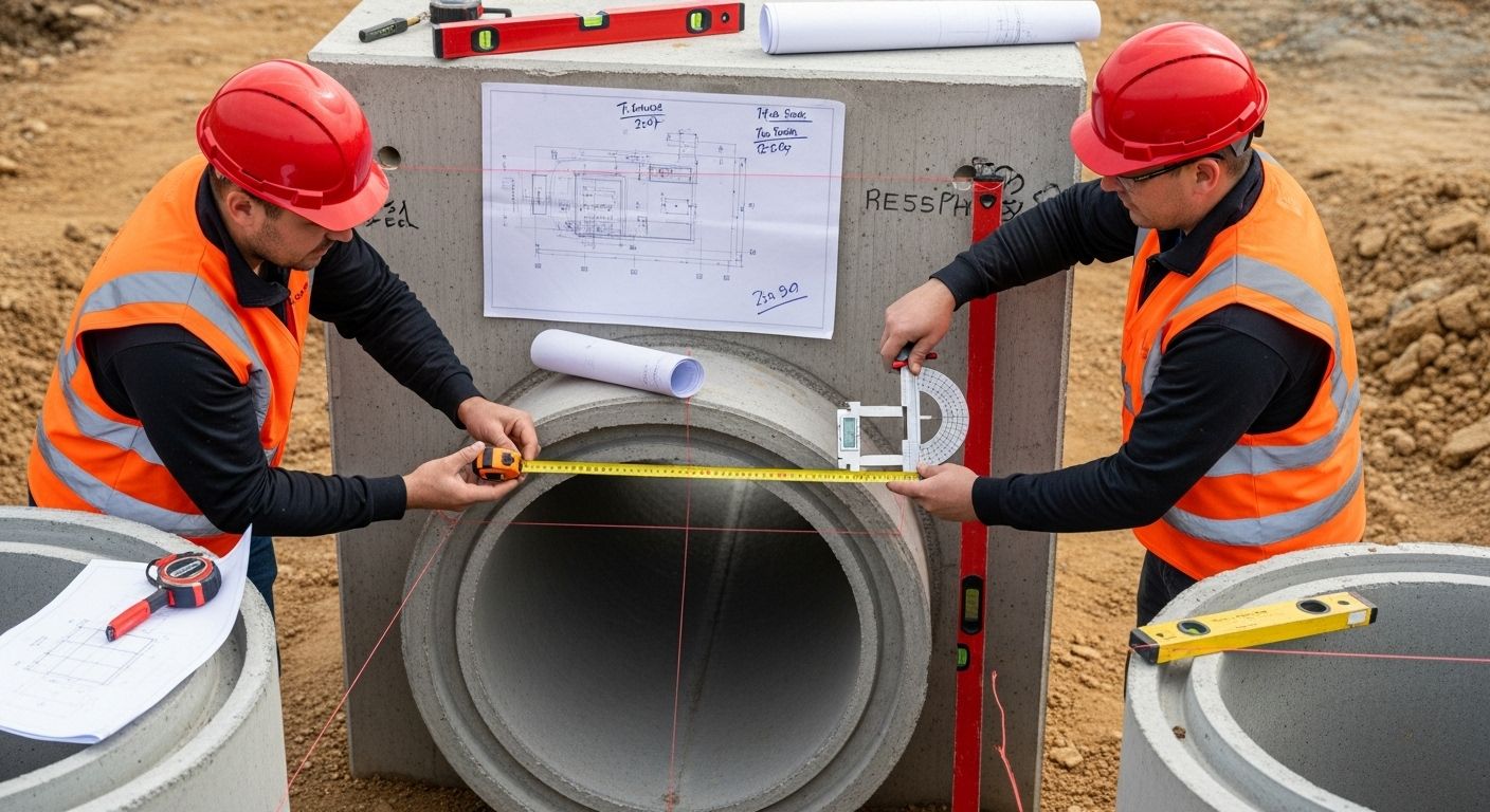
How to Specify Headwalls for Effective Drainage Solutions

Designing reliable drainage infrastructure in Canada takes more than strong materials or well-placed culverts. In practice, precise elevation mapping, Canadian hydrology datasets, and rigorous documentation often determine success or failure before construction begins. While concrete and hydraulics matter, it’s the Canadian-specific site investigation and code-aligned planning that drive resilience, safety, and long-term durability.
Table of Contents
- Step 1: Identify Site Requirements And Constraints
- Step 2: Determine Hydraulic Design Parameters
- Step 3: Select Suitable Headwall Types And Materials
- Step 4: Specify Design Dimensions And Configurations
- Step 5: Review Codes, Standards, And Local Guidelines
- Step 6: Conduct Final Quality Checks And Approvals
Quick Summary
| Key Point | Explanation (Canada) |
|---|---|
| 1. Comprehensive site assessments are essential | Topographic survey, geotechnical review, utilities, and environmental sensitivities—documented to provincial/municipal expectations. |
| 2. Accurate hydraulic design parameters are crucial | Use Canadian Engineering Climate Datasets (ECCC) and IDF_CC to derive IDF curves/design storms. |
| 3. Material selection impacts drainage performance | Choose materials for freeze–thaw and de-icing salts; concrete per CSA S6 context and CSA A23.1/A23.2 durability classes. |
| 4. Dimensional specs must match hydraulics | Headloss, entrance/exit geometry, scour protection per TAC/provincial manuals (e.g., BC MoTI TAC Supplement Ch.1000). |
| 5. Regulatory compliance is mandatory | Coordinate with DFO’s Standards & Codes of Practice (Fisheries Act) and local authority standards. |
Step 1: Identify Site Requirements and Constraints
Begin with a structured site assessment: detailed survey (including precise elevation mapping), utilities, soils, groundwater, riparian areas, and construction access. For hydrologic context, compile historic/extreme climate indicators using Environment and Climate Change Canada’s Engineering Climate Datasets and training resources such as IDF Curves 101. Where fish habitat may be affected, document watercourse characteristics and timing windows aligned to the Fisheries Act review pathway and DFO’s codes/standards.
Document at minimum:
- Local IDF/return periods (ECCC station and record length)
- Geotechnical properties (erosion potential, frost susceptibility)
- Sensitive areas/fish habitat and permitting triggers
- Existing municipal/provincial design expectations
Step 2: Determine Hydraulic Design Parameters
Turn site data into design storms and flows. Use ECCC station data from the Engineering Climate Datasets or open datasets such as Short-duration IDF statistics, and evaluate climate-adjusted scenarios via IDF_CC. Size inlet/outlet works, evaluate headloss and tailwater, and check erosion potential. Align return periods and risk with provincial practice (e.g., BC’s MoTI TAC Supplement, Ch.1000) and applicable municipal criteria (e.g., City of Surrey Design Criteria Manual).
Step 3: Select Suitable Headwall Types and Materials
Choose materials for Canadian exposures: freeze–thaw cycles, de-icing salts, abrasion, and impact. Concrete should be specified to the correct exposure class and performance requirements per CSA A23.1/A23.2 (2024) with awareness of recent durability updates (see industry summary of 2024 changes). For structural context and buried structure interfaces, reference the CSA S6 (CHBDC) and provincial manuals (e.g., BC Hydrotechnical – Drainage & Culverts <3.0 m).
- Reinforced concrete: robust; specify air-void system, cementitious content, and chloride durability per CSA A23.1.
- Polymer concrete composites: corrosion-resistant, light, rapid to install; useful for salt and freeze–thaw environments.
Step 4: Specify Design Dimensions and Configurations
Translate hydraulics into geometry: inlet face, flare/wingwalls, aprons/toe-walls, and outlet protection. Size energy dissipation and riprap to provincial or TAC guidance (e.g., BC’s Ch.1000; TAC papers). Where applicable, coordinate with bridge/culvert provisions under CSA S6 (buried/culvert end treatments). Maintain constructability and inspection access per provincial/MTO guidance (e.g., Ontario’s Culvert Inspection Guide).
Step 5: Review Codes, Standards, and Local Guidelines
Compile a compliance matrix spanning federal, provincial/territorial, and municipal layers:
- Hydrology & climate: ECCC Engineering Climate Datasets, IDF_CC Tool, and related IDF datasets.
- Fish and habitat: DFO Standards & Codes of Practice and culvert-specific code of practice (web / PDF).
- Design practice: Provincial TAC supplements/manuals such as BC MoTI TAC Supplement Chapter 1000 and program pages for BC drainage & culverts; Ontario references such as the Highway Drainage Design Standards.
- Materials & structures: CSA A23.1/A23.2 (Concrete), CSA S6 (CHBDC); see also SCC/CSA listings (e.g., SCC database entry).
- Municipal criteria: Local design manuals (e.g., Surrey; typical Ontario municipal standards example).
Step 6: Conduct Final Quality Checks And Approvals
Before tender or fabrication, execute a QA/QC cycle: check geometry against hydraulic performance, verify materials/testing to CSA A23.1/A23.2 and exposure class, confirm hardware/cover details, and validate scour protection sizing. For works in/around water, confirm DFO pathways (self-assessment, code of practice applicability, or project review) using the DFO standards portal. Maintain an auditable record of assumptions, datasets (station IDs, IDF versions), and approvals.
| Verification Step | Description | Purpose |
|---|---|---|
| Hydrology dataset log | Record ECCC station, IDF version/date, climate-adjustments | Traceability and comparability |
| Geometry & headloss check | Validate inlet/outlet, wingwalls, apron/toe-wall, tailwater | Capacity and energy dissipation |
| Material & exposure class | Concrete performance/corrosion requirements per CSA A23.1 | Durability under salts & freeze–thaw |
| Scour/armouring design | Riprap gradation and geotextile selection per provincial/TAC | Bank/channel protection |
| Environmental compliance | DFO codes of practice/project review determination | Fisheries Act adherence |
| Inspection/maintenance access | Conform to provincial/municipal inspection expectations | Lifecycle performance |
Take the Uncertainty Out of Headwall Specification
Canada’s realities—freeze–thaw, de-icing salts, variable hydrology, fish habitat constraints—demand headwalls designed to local data and codes. The steps above show how site assessments, Canadian IDF datasets, and standards-based detailing de-risk projects. If you need products that install fast and stand up to harsh conditions, consider advanced polymer concrete solutions.
Next step: Explore CIF Composites headwalls engineered for Canadian exposures and agency expectations, or contact us for project-specific specifications.
Frequently Asked Questions
What factors should I consider when identifying site requirements for headwalls?
Survey control and elevations, ECCC climate/IDF context (Engineering Climate Datasets), soils/frost susceptibility, utilities, fish habitat triggers (DFO standards/codes), and applicable provincial/municipal manuals.
How do I determine the hydraulic design parameters for headwalls?
Derive design storms from ECCC/IDF tools (e.g., IDF_CC), build hydrologic/hydraulic models, then size inlet/outlet geometry and scour protection per provincial/TAC guidance (e.g., BC MoTI TAC Supplement).
What materials are suitable for constructing headwalls?
Reinforced concrete designed to CSA A23.1/A23.2 exposure class requirements, and polymer concrete composites for high corrosion/freeze–thaw resistance. Structural interfaces should respect CSA S6 context for buried structures/end treatments.
Why is it necessary to review codes, standards, and local guidelines during headwall specification?
To align with Canadian climate datasets, structural and material standards (CSA), and environmental obligations (DFO). This avoids redesign, accelerates approvals, and ensures lifecycle performance.
Recommended
- ECCC – Engineering Climate Datasets (IDF & climate data)
- IDF_CC – Climate-adjusted IDF tool (Canada)
- DFO – Standards & Codes of Practice (Fisheries Act)
- CSA A23.1/A23.2 – Concrete (2024) | CSA S6 – CHBDC
- BC – Hydrotechnical: Drainage & Culverts <3.0 m | Ontario – Highway Drainage Design Standards
- CIF Composites – Headwalls